The last time I built any armor was 15 years ago and the best
Sherman kits we had at the time were the Tamiya and Italeri kits. Recently,
I thought it would be fun to revisit armor and do a few quick Sherman builds.
It seemed like a nice change of pace from some of the more involved projects
that I’ve been doing. When selecting the kits, I thought I would try the
more recent Dragon releases because they were the newest and I reckoned
better than the older Tamiya and Italeri versions. I was quite surprised
to discover that these kits are not particularly easy to construct and
require a fair bit of trial and error in fitting the pieces together.
In some ways, building these kits reminds me of old craftsman railroad
kits where you get a bunch of universal parts and it is basically up to
you to figure out how to reshape and fit them together. The instructions
for the Dragon kits are rather spartan and I have found them difficult
to follow because they are drawn with so many “sub-assembly” and “option
boxes”. This is the only time I can ever remember that I have had to actually
use a pen and mark off the parts and assemblies. This is compounded by
the fact that the sprues contain a myriad of unused parts that are intended
for other versions. Some of these extra parts look very similar to the
necessary parts. This is a nice benefit for growing your spares box, but
after having worked with these kits for while, I have come to the conclusion
that fewer, but better designed parts would be a nice feature. I now understand
why I still see so many completed Tamiya Shermans in the online galleries.
However, now that I’ve started with these kits, I’m going to stay with
them. I think they have a lot of nice detail features and I like the fact
that I can cover so many variants.
As I have worked my way through several of these kits, I have
devised some methods that work for me and I thought it would be helpful
to share them with other builders. These techniques are focused on improving
the basic structural construction and overcoming those aspects that I feel
are shortcomings of the kit. For the most part, my goal has been to work
with what is supplied in the kit. As a preface, this is not an article
on detailing the Sherman. To that I defer to the many great sources that
are available to Sherman devotees.
The box of a Dragon Sherman is significantly larger than the
Tamiya Sherman, Fig. 1. The Dragon box is jam packed and it is funny how
hard it is to put everything back in if you take everything out for an
inspection. It becomes immediately apparent that a good pair of sprue
cutters will be indispensable, Fig. 2.
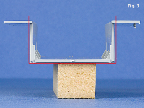
All the Dragon Shermans that use the heavy VVSS share the same basic lower
hull design. The only differences are the details on the underside of the
hull. From my experience, it is common to find the lower hull a bit less
than square, Fig. 3. Every hull seems to be different in this distortion
so check each side with a square.
My solution is to make a diagonal cut part way through the corner of the
bottom and side, Fig. 4. With a little pressure, you can bend the side outward
a bit and bring it to square. I then use sprues to brace the structure and
reinforce all joints with my mixture of Zap-A-Gap and dental acrylic resin
powder, Fig. 5. The result is a very nice rigid structure. Even if everything
is square right out of box, I like to add similar supports. Of course this
method of bracing will not work if you are going to be detailing the interior.
The rear plate for the lower hull needs a little special attention. Because
Dragon has used the same lower hull side, each rear plate has been adapted
to fit the specific version. Fig. 6 is the rear plate for the newer M4
Normandy and Composite PTO. Fig. 7 shows the rear plate for the M4A3E8. The rear
plate in Fig. 8 is what is supplied for the M4A3 which is the most challenging
because it really lacks any sort of positive lock for location. You will
need to do some filling and sanding no matter which back you use, but my
experience has been that non of them are quite wide enough to let you simply
fill in the gap and then sand it smooth so that it is flush with the side.
My approach has been to dress the side of the rear plate to make it flat
and then add a .010” piece of styrene to each side, Fig. 9. This sands down
better than filler and provides a better surface for gluing the idler wheel
mounts.
The horizontal pieces under the sponsons sometimes need to be squared up
as well. A little judicial pressure is usually enough to bring them into
square. This is fairly easy because the box has been made nicely rigid in
the previous step. After the sponson floors are squared up, you can cement
on the rear extensions. I have generally found the sponson floors to have
a bulge in the center which distorts the upper hull side, so I carefully
sand this area flat, Fig. 10. Go slow and check fit the lower and upper
hull. Always check and recheck. Also give the other flat surfaces a little
sanding.
I am not particularly enamored with the way Dragon has chosen to mount
the M4 suspension, Fig. 11. There are too many pieces and with each step
there is additional potential for error and misalignment. I feel that
in this respect, the Tamiya hull in Fig. 12 is a far better method. The
Tamiya hull provides perfect alignment and spacing of the bogies as well
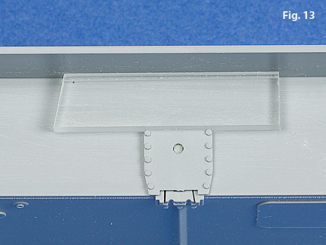
as the rear idler and front drive sprocket. To help cement the mounting
plates more uniformly, I use a spacer cut from a piece of clear acrylic,
Fig. 13.
The construction of the suspension bogies is also more involved than the
Tamiya method, Fig 14. Dragon has elected to make the suspension arms
a separate structure which is fine, but they molded them in one piece so
that their movement is not prototypical, Fig. 15. The only advantage to
the Dragon system is that it provides an actual separation between the
suspension bracket and the arms which looks a little better, but again,
it is another potential for misalignment. The fixed position of the Tamiya
method allows the suspension brackets to be cemented perfectly vertical
along the hull sides. The rocking motion of the Dragon system plus the
slop in the fit of the bracket to the mounting plate means that the vertical
alignment is strictly visual.
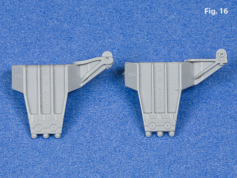
The Dragon kits using the heavy M4 VVS suspension give you a choice of
two types of return roller support arms, Fig. 16. The early straight arm
on the right and the angled arm on the left. You should consult your references
in deciding which type to use.
Dragon molds their components differently to minimize ejector pin marks,
but this means that there are a lot more sprue attachments to clean up,
Fig. 17. This becomes extremely pesky if they are on parts that are supposed
to be perfectly round. In my case, I resort to using a lathe to clean
them up.
Most of these kits are supplied with a choice of open spoke wheel or a
solid spoke type. The open spoke wheel fits better and is less of a problem,
however, I still use the lathe to clean them both up and make sure the
tires will sit flat. The solid spoked wheel consists of two pieces and
takes more finesse. If you want
the spokes to line up, then don’t do what I do. If on the other hand,
you subscribe to the theory that you can only see one side at a time, then
I suggest you make the assembly much easier by removing the alignment tab,
Fig. 18.
The solid spoke wheel does not fit on the axle, Fig. 19, so you will need
to drill it out, Fig 20. The method that I use to clean up these round
components is to turn an arbor that I can press fit the wheels onto and
then quickly clean up the outside of the tire, Fig. 21.
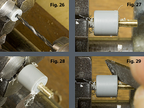
The solid wheels are also too wide for the axles, Fig. 22, so you need
to face off a portion from both sides.
The construction of a tracked vehicle suspension can be very repetative
and there can be a tendancy to hurry. Spend a little time and check which
side of the road wheels face the the front. When placed onto the axles
the side facing up will go on the inside. One side of the spoked wheel
has a recess that helps keep it free from cement. This is the side that
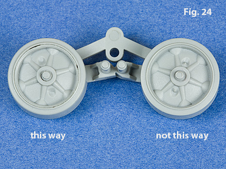
should face to the inside, Fig. 23. One face of the solid spoked wheel
is molded with the wheel and looks much better, this side should face towards
the outside, Fig. 24. A spring paper clip is a nice aid in cementing the suspension arm assembly
together, Fig. 25.
The same process is used to finish off the return rollers, Figs, 26, 27.
Check the return roller width with the tracks that you are using. I planned
on using Tamiya T48 tracks and the return rollers seemed a bit tight, so
I reduced the width, Fig. 28. In any case, you will want to radius the
inside of the roller to match the outside. I do this simply with a quick
pass with a file, Fig. 29.
The spring assembly is in two pieces and I have found it easier to hold
if you assemble it first and then clean up the sprue attachments, Figs
30, 31.
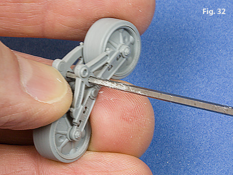
The suspension arm assembly does not fit well into the suspension brackets
so I used a reamer to enlarge the holes, Fig. 32. Before everything is
buttoned up, I like to lay it all out so I don’t get anything backwards,
Fig. 33. I usually remove the locating pins from the inside bracket half
and sand both mating surfaces. However, some modelers may feel more comfortable
using the locating pins.
After the suspension bracket halves are glued together, you will need
to clean up the glue joints, Fig. 34. A little extra detailing can be
added by drilling out the mounting holes for the return roller arms Fig.
35. I made a quick drilling jig from sheet brass (the construction of
the jig is described here).
Note the center line marked on the jig. I use the kit supplied support
skids, but there are some very nice aftermarket ones available.
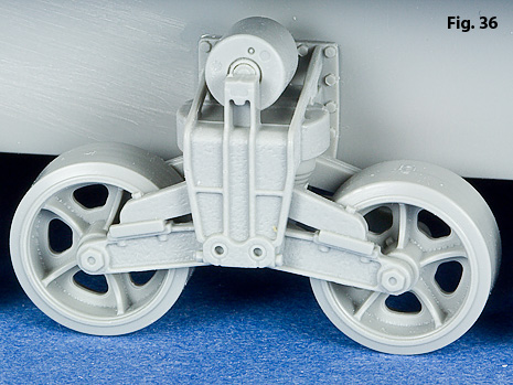
The Dragon kits of the early Shermans use a very nice M3 suspension bogie,
Fig. 36. This bogie is supplied in both the M4A1
DV and M4A2 DV (Cyber-Hobby
Sherman III DV). While both kits share the same bogie, but the hull and
mounting are different. The mounting plates along with some very nice
rivet detail is molded into the M4A1 DV hull, Fig. 37, while the M4A2 DV
kit uses a typical Dragon lower hull, Fig. 38.
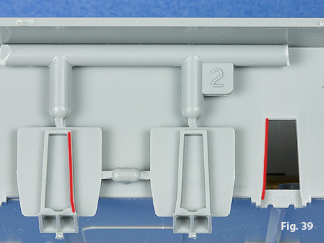
The M4A2 DV (Sherman III DV), uses separate mounting plates and these
plates are specific to each side, so double check to make sure you are
using the correct plate, Fig. 39. The plates have a bit of side-to-side
slop. You can check the alignment of the plate with the bracket that is
molded into the bottom of the hull, Fig. 40.
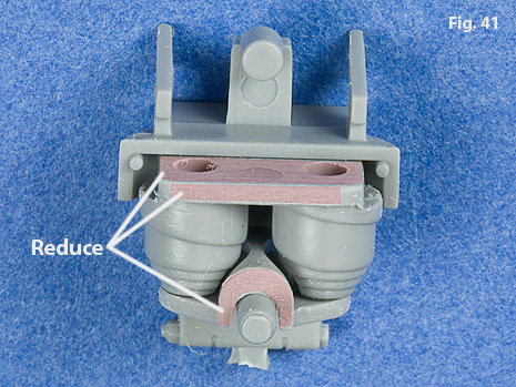
The spring and platform fit a little too tightly into the suspension bracket
so I found a few passes with some sandpaper on the indicated surfaces allows
the two bracket halves to close better, Fig. 41.