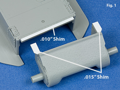
Dragon has created a number of final drive and differential housings. Depending on the kit, you might be offered several choices. Additional information on Dragons’ various final drive and differential housings can be found here and here. I have found that you can improve the fit between the transmission, bold strip, and the upper hull, it helps to shim the transmission in the area indicated in Figs. 1, 2.
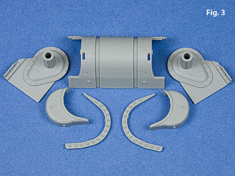
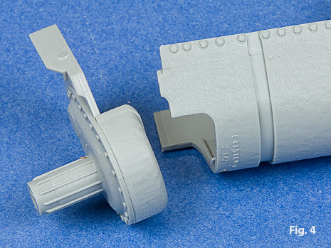
There are two styles of the early three piece housing. The earliest version with the flush bolt strip has individual pieces for the differentials, Fig 3. I find it easier to cement the differential cover/side plate to the differential housing first, before joining it to the main body of the transmission cover, Fig. 4.
The resulting assembly leaves a number of joints that need to be filled, Fig. 5. My favorite method of eliminating these joints is to fill them with Mr. Surfacer 500. The Mr Surfacer is allowed to dry for an hour and then the excess is removed and smoothed with a cotton swab moistened with 90% isopropyl alcohol, Fig. 6.


The new three-piece housing included in the Normandy kit is really well done except for the seams that run across the front, Fig. 7. These can be easily removed with the technique described here. This transmission housing is especially nice because there are no other seams to fill, Fig. 8.


You will need to open up the locating holes for the tow shackle mounts, Fig. 9. Don’t make the holes too big because the pins on the mounts are not that big. I prefer to only open the top hole and remove the lower dimple from the shackle mount. This way I have the vertical position established but I still have more freedom for alignment.
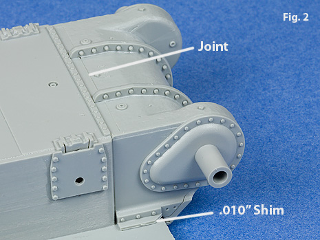
At this point, I like to cement the transmission to the lower hull. I use a .010” shim as shown above in Fig. 2. With the transmission in place, it is easy to correctly position the bolt strip, Fig 10. Note that there is a definite lip behind the transmission castings and the bolt strip.


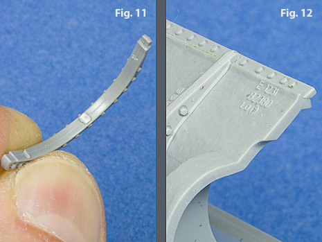
A little extra care is necessary to properly fit the pieces that make up the flanges. The first step is to thoroughly remove all the burs and ridges from the underside, Fig. 11. When done properly, the flange piece fits nicely over the bolt strip, Fig. 12.
The joint between the flanges should be scribed in, Fig. 13.

One of the poorest renderings of a transmission housing is Dragon’s previous version of the late model housing included in the M4A3 and M4A3E8 kits. This housing does not accurately replicate the covers on the side of the housing. The covers need to be considerably larger and positioned differently. For a further discussion of the issues with this final drive assembly, go here. I have found that the sides of the late model housing need to be shimmed out from the inside to provide a better fit with the lower hull, Fig. 13.
The bolt strip on the transmission housing is another challenge. I have found it easier to get the correct positioning if you cement the transmission housing in place first and then work out the angle of the bolt strip with both the upper and lower hull in the correct position. I like to give myself a little fudge room here and make sure there are no hang-ups between the upper and lower hull halves so I cut a small notch in the lower hull half and bevel the underside of the forward sponson shelf, Figs. 14, 15. This allows me to slide the lower hull half fore and aft easier.


Both of my PTO kits had a flaw in the bolt strip and I added back the missing bolt with a piece of .028” brass wire, Fig. 17. Some modelers may want to write Dragon Care and get a new bolt strip.
In the Normandy kit there is quite a bit of space between the side of the transmission housing and the hull. A little piece of styrene here does the trick nicely, Fig 18, 19.


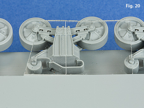
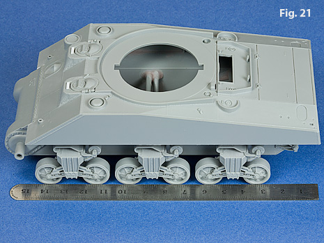
A few simple guides can help when cementing the bogies in place. To help check if the suspension bracket is vertical, I simply scribed a line in a piece of acrylic and it works perfectly as a square to check the alignment of the bogey assembly, Fig. 20. A straight edge can be used to get a quick check to verify the fore and aft alignment, Fig. 21.
Dragon has chosen to mold the drive sprocket assembly in four pieces, Fig. 23 rather than doing it like Tamiya’s two piece method, Fig. 22. In addition, the drive sprocket is quite sloppy when mounted to the tank. To make the fit of the sprocket much more solid, I glue in a piece of ¼” styrene tubing, Fig. 24.


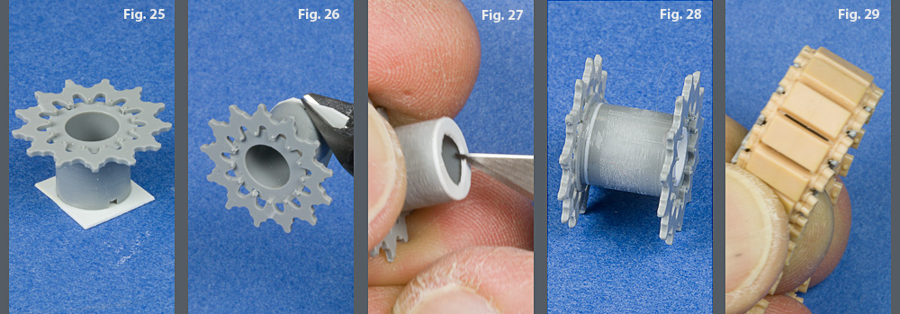
The fit of the sprocket rings to the hub parts is sloppy as well. I cement each sprocket and hub piece together first, making sure they look centered, and then assemble the two halves. Check the fit of the tracks that you are using. The sprocket is too narrow to accommodate the new DS tracks supplied in the Dragon kits. I have found that the fit can be improved by inserting a shim of .015” styrene, Figs. 25 – 29. The shim styrene is glued in place and then cut back.
I open up the keyway a bit so that I can adjust the alignment better. You can easily check the alignment by making sure that four teeth of the sprocket contact a flat surface without rocking as in Fig. 30. Rotate the sprocket and check it on several different sets of teeth. A quick check for fit of the sprocket can be done by making sure it is centered with the road wheels, Fig. 31.


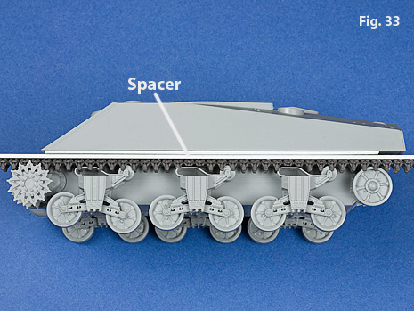
When I have the opportunity, I dodge the whole bullet and use a Tamiya sprocket which can easily be drilled out to fit very nicely, Fig. 32. I made a jig from a section of Academy track cemented to a piece of styrene. I combine the jig with a spacer and this helps me position the rear idler, Fig. 33.

To the dismay of many builders, I don’t mind using some of the vinyl tracks, so the horizontal positioning of the idler isn’t as critical as the vertical positioning. You can sight down to check the alignment of the idler wheel by laying a ruler against the road wheels, Fig. 34.
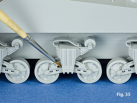
With the tank resting solidly on a flat surface, I lock the suspension assembly down with a bit of cement, Fig. 35.

Well that’s about it for the basic hull and suspension. At this stage, I have a nice solid, straight structure that can act as a palette for all the details to follow. As you probably have deduced from this article, and for those who know me, I’m pretty well fixed on the fact that the basic shapes need to be correct and the structures need to line-up properly. This takes a little more doing here because of the way these kits go together. In some regard, I feel the Dragon kits are “over engineered,” which is good if it yields a better rendition. However, if the same look can be achieved with a single part, as in the case of the drive sprockets, then you have the potential for a sturdier and more accurately aligned part with the single structure.