Dragon has done a very nice job with their turrets. All the current turrets
benefit from updates and refinements. The various Dragon kits provide
enough different turrets to allow you to build any example that is necessary.
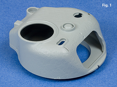
The new early low bustle 75mm turret, Fig. 1, is supplied in the M4A1
Direct Vision kit without the smoke mortar port and with the smoke mortar
port in a number of other kits. Appliqué armor and the early M34A1 mount
are included in the Normandy kit, Fig. 2.

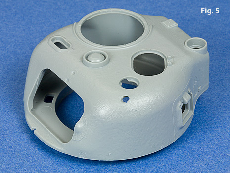
The PTO Composite M4 kit supplies both the low bustle, Figs. 3, 4, and
the high bustle turrets, Figs. 5, 6. Both turrets have cast cheek armor,
oval loaders hatch, and pistol port. Unfortunately, in the original issue of this kit, Dragon neglected
to include the lower turret half for the high bustle turret so you will
need to write to Dragon
Care to obtain the piece. The instructions for
the turrets in the PTO kit are sorely lacking and it is necessary to have
additional information if you want to assemble them correctly. For the
most part, the instructions indicate the assembly of the high bustle turret,
but they call out to use the same lower turret half for both turrets.
I suspect that if Dragon had not cut the lower turret half off the second
“B” sprue, the part would be numbered (B31) which would be similar to the
same piece supplied with the 105 turret, Fig. 12, since the sprue layouts
are identical. I have modified some Normandy instructions which hopefully
do a better job of showing how to assemble the low bustle turret, here.
Despite the fact that the instructions have “blued-out” most of the first
“B” sprue, the “B” numbers in my revised instructions refer to the first
“B” sprue.


The low bustle turret with cast cheek armor that is supplied with the
Dragon PTO kit, Figs. 3, 4, was relatively rare. The turret can be easily
modified to a more common version without the loaders hatch and pistol
port, Fig. 7.
Each turret is supplied with the appropriate mount, Figs. 8 – 11.
Fig. 12 shows the mount for the 105mm howitzer.
There are some assembly steps that can be applied to all the turrets.
Generally, I like to: 1) assemble the upper and lower halves together;
2) fill the seams 3) make any modifications such as fill the smoke mortar
port or the pistol port; 4) re-texture the smoothed out areas (using this
technique) and add back the mold parting line; 5) attach the lift rings;
6) prime the cast areas with a lacquer primer for texture; 7) add the rest
of the components and details.
My technique for creating a lip around the smoke mortar port is to
use a piece of styrene sprue that I machine and cement into the opening.
I cut the piece leaving a slight raised lip that I finish off with a bevel,
Fig. 13.


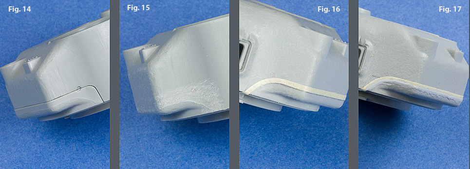
The fit between the upper and lower halves of the 75mm turrets is not
that good, Fig. 14. Dragon makes an attempt to incorporate the mold parting
line in the lower half, but because of the poor fit between the two halves,
the area needs to be filled and reshaped, Fig. 15. I then re-texture the
area using the technique described here.
I use a thin piece of masking tape to lay out the cast parting line, Fig
16. Several coats of Mr. Surfacer 500 are brushed against the tape, Fig
17.
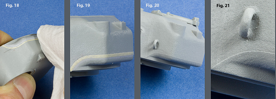
After allowing the Mr. Surfacer to dry for about an hour, I use a paper
towel moistened with 90% isopropyl alcohol to blend the Mr. Surfacer and
level it with the tape, Fig 18. Rub the towel perpendicular to the tape
rather than parallel. The result is shown in Fig. 19. After the tape
was removed, the portions of the turret that do not have cast texture are
masked off and then the turret is sprayed with a lacquer primer, Fig. 23.
The final coat should go on relatively dry. After the primer is dry, I
knock down a bit of the texture with a scuff pad. The finished line is
shown in Fig. 20. The texture of the lacquer primer can be seen in Fig.
21.
It is best to look to your reference material for placement and angle
of the lift rings. I use a variety of methods to locate the position
of the lift rings so that they are vertical and equal in height, Fig. 22.
This is the lacquer primer that I like, Fig. 23.


I have my own sequence for assembling the 75mm mount. When cementing
piece B20 into the turret, check to insure that it is parallel to the turret
face, Fig. 24. Look at the space indicated in red. This is critical because
it provides the support and positioning of the mount.
Dragon produces two versions of the M34A1 mount. Check your references
and make sure your using the correct mount. The two versions are shown
in Fig. 25. The later version (on the right) does not have the bolts on
the side and uses a slightly wider mantlet. Dragon depicts the wider mantlet
with a heavier cast texture which can be easily distinguished when compared
to the smaller version. In any case, make sure you use the correct mount
and mantlet combination.


I like to cement the mount into place first, Fig. 26. The barrel is nicely
molded but needs to be sanded smooth to eliminate the seam. Then the mounting
piece is cemented to the end of the barrel, Fig 27.
I then cement the barrel to place using a simple paper guide and a block,
Fig 28. This gives me a pretty good idea that I am perpendicular to the
backside of the turret bustle.
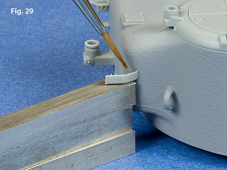
I use a simple spacer arrangment to cement on the .50 caliber barrel stowage
brackets, Fig 29. These just happen to be lathe tool bits, but you can
use what ever you have that works. This insures that both brackets are
the same height and are straight.
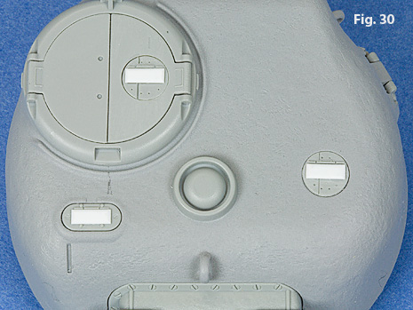
I cut my own periscope lids from .020” x .080” styrene strip, Fig. 30.
I find it is faster to cut them and bevel them than it is to clean up the
molded ones included in the kit. I think they come out squarer as well.
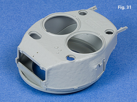
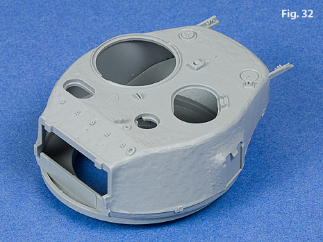
Dragon also provides very nice renderings of the both 76mm turrets, Figs.
31, 32.
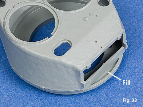
Both 76mm turrets have an open space under the mount that needs to be
filled, Fig. 33. I cemented a piece of .015” sheet over the space, Fig.
34.
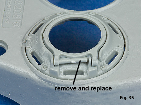
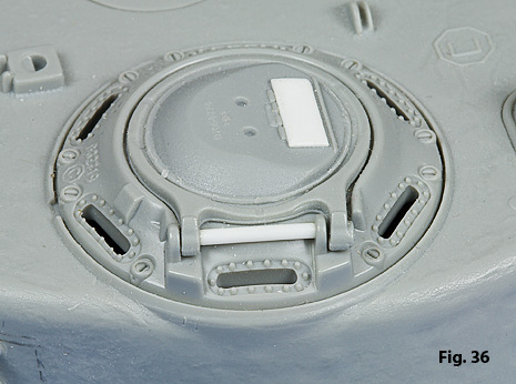
The hinge pin of the hatch on the direct vision cupola is poorly represented,
Fig. 35. It should be removed and replaced with a piece of styrene rod,
Fig. 36.
Keeping in mind that all kits have issues, and certainly the Dragon kits have their share, I think they look very nice when assembled, especially the Normandy and Composite PTO. I feel that the details are very crisp and sharp. With the exception of the final drive housing and transmission issues, I think Dragon does a good job rendering the shapes correctly.
I hope this article has been helpful. I’ve enjoyed sharing some of what I’ve learned in building these kits.