The rib and fabric detail for the rudder was simulated with .005” copper wire. The wire was laid into groves that had been scribed into the rudder surface, Fig. 1. Cyanoacrylate cement was built up along the sides of the wires and then contoured. The surface was primed and left grainy, Fig. 2. The trim tab actuators where machined and shaped with a file from brass rod, Fig. 3. The pin allows precise location and a press fit for a clean joint, Fig. 4. Also note that the port elevator trim tab actuator is located underneath while the starboard side has the actuator on top. The rudder control horns were cut from .005" brass and the patch covers were cut from silver vinyl tape.


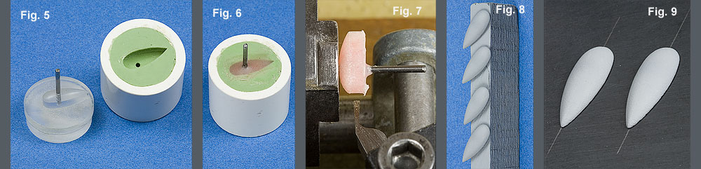
A pattern for the wing cannon blisters was created from acrylic rod stock. The pattern incorporated a pin, Fig. 5. A rubber mold was made of the pattern. A pin is placed into the mold and then the mold is filled with self curing dental resin, Fig. 6. The casting is faced off on the lathe, Fig. 7. The upper extension of the pin is cut off and finished down. The blisters were given a coat of lacquer primer, Fig. 8. The finished blisters are mounted on the wing, Fig. 9.
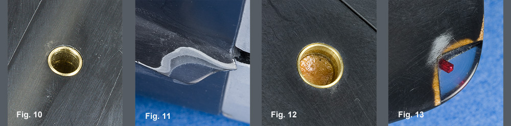
Several techniques were used for the various navigation lights. The round lights were created with brass bezels, Fig. 10 & 12. These would later be fitted out with machined acrylic lenses. Because the entire elevator structure had been created from clear acrylic, it was only a matter of exposing and polishing the portion that would be masked off for the rear navigation lights, Fig. 11. The wing tip lights were triangles of acrylic that were drilled and painted with transparent acrylic paint, Fig. 13.
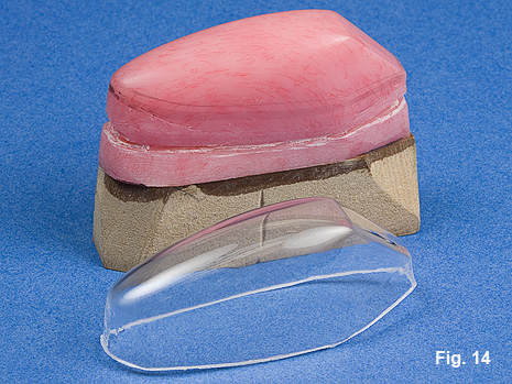
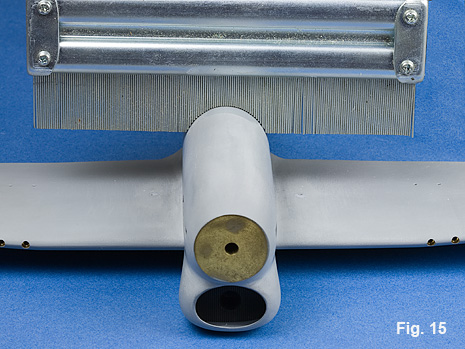
A form for the canopy was shaped from rock maple which worked pretty well, but did not give me quite as smooth a finish as I would have liked. I duplicated the wooden pattern in highly polished dental resin and this worked much better. The finished canopy was formed from .060” sheet acrylic, Fig. 14. The first step in fitting the canopy to the fuselage was to determine the radius of the area around the canopy. A contour gage works perfectly for this task, Fig. 15.
A dowel of corresponding size is wrapped with sandpaper and used to shape the canopy to fit on the fuselage, Fig. 16, 17.


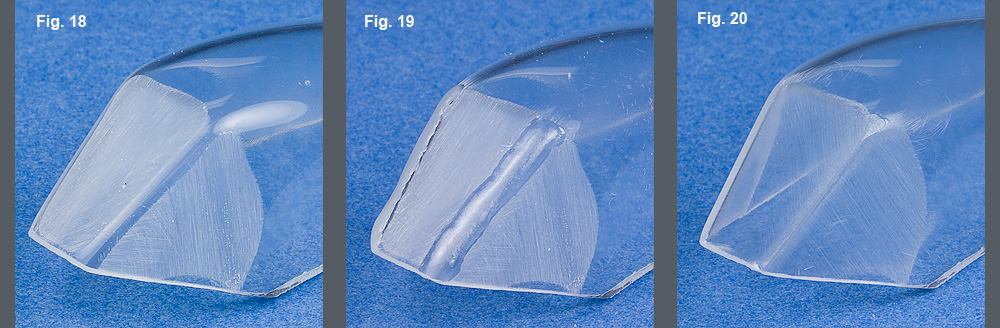
The problem with a vacuum formed canopy is that the outside of the angles are not sharp and the windscreen panels are not perfectly flat. The first step is to sand the windscreen panels flat, Fig. 18. A mixture of cyanoacrylate and clear dental resin powder is applied to the corners, Fig. 19. The excess is sanded down and finished off, Fig. 20.
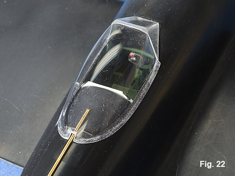
The canopy was sectioned and the windscreen cemented in place. The flare at the bottom of the canopy was formed with a mixture of cyanoacrylate and clear dental resin powder. The area of the fuselage where the canopy will finally rest was covered with bare metal foil. The dental resin and cyanoacrylate mixture was flowed around the base of the canopy, Fig. 21. The canopy was removed and the flare finished down, Fig. 22.

The canopy rails were machined from brass, Fig. 23. The canopy was polished inside and out to remove any distortions. I don’t use any coating over the clear acrylic as I think it does not look prototypical.


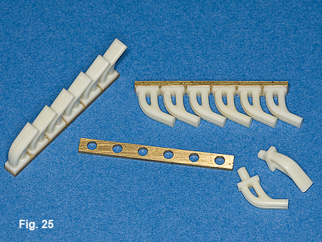
The spinner was turned from acrylic. Holes were drilled in the spinner and slots were milled in order to accept the prop blades. A piece of sheet styrene was used to form the back of the spinner. The prop blades were cut from .010” sheet brass and soldered to brass rod. The blades were then given a twist and the front surface leaded with solder and contoured, Fig. 24. I created a brass master pattern for an exhaust stack and Roy Sutherland cast some beautiful resin copies. The resin exhaust stacks were mounted on a machined brass manifold, Fig. 25.

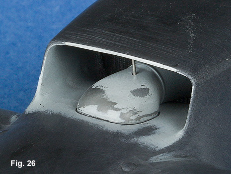
The carburetor ducting that exits out through the back of the radiator was created from a piece of acrylic rod stock, Fig. 26. An actuating rod that controls the chin door passes through the duct.

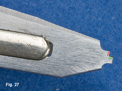
A lip around the gear well needed to be created, Fig. 28. This was done by modifying a scalpel blade, Fig. 27. The green line indicates the safe side while the red line indicates the cutting surface. The safe, non cutting side is run against the inside of the gear well opening.