When everything was properly positioned, a mixture of cyanoacrylate and dental resin powder was flowed around the brass rod where it exited the wing. When set, the rod was cut off and the remaining hole was filled. The portion of the rod protruding from the wheel well was cut off.
The critical element in the gear well is the piece of brass tubing that locates the main landing gear leg, here shown circled in red. The method that I used to position the tubing is shown in the diagram below. Holes were drilled completely through the gear well and the wing. The holes are slightly oversized to allow for angulation of the tubing. The brown rectangles in the diagram represent blocks of wood. The blocks were drilled with a hole to accept the tubing. The hole was drilled at an angle that corresponded to the outward angle that the gear is pitched. A note here: Bentley’s drawings indicate an angle of 3°, however in my opinion, that makes the gear look a little to splayed out. I used 2° instead. The airframe was blocked at the points indicated by the red arrows. The forward rake of the gear is determined by the elevation of the tail. I took this angle from Bentley’s drawings, which in reality has the tail higher than the diagram.


The Tempest landing gear ranks as one of the most complicated bits of machining that I have ever done. In theory, it is simply two legs hinged together to function as a parallelogram. However, the incorporation of an internal spring/shock seemed to inspire the designer to new heights of complicated shapes. In fact, the construction of the landing gear is what put me off of this project years ago. No matter how I looked at it, I could not figure out a way to “simplify” the gear and maintain the characteristic intricacies. Determined to get past this step, I decided to break the gear down to its elemental state and just start whittling down the individual components. The upper leg is a straight turning, while the lower leg is made up of a straight turning with yoke fabricated from a milling and a turned axle. The major components are held together by a two piece brass jig. The brass jig fits into the slot of a second jig made from acrylic sheet stock. The acrylic jig is drilled to locate the axle and has a block to establish the extension of the finished gear, Fig. 1. The breakdown of the major individual parts is shown in figure 2.


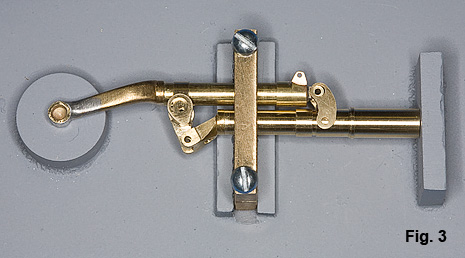
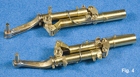
Figure 3 illustrates how the jig is used to locate the individual components. Everything is pinned together and, where necessary, soldered. Cutting to the chase, the completed gears are shown in figure 4. I will not even admit how many hours I have in these gears. Every piece is a combination of lathe, mill, and file. If you would like an example of how these processes are used together, an example of the fabrication of one of the gear pieces is shown here. Although they are fully functional, I used a bit of cyanoacrylate cement on the shock shaft to secure the position.
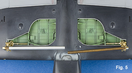
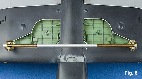
Alignment of the two main landing gear legs when mounted was handled with the method shown in figures 5 and 6. Two pieces of brass rod were drilled to fit over the strut axles. A piece of brass tubing was slid over one rod, Fig. 5. The rods were aligned and the tubing slid over the opposite rod, Fig. 6. A little cyanoacrylate cement secures the gear in place. The gear retraction rods were machined from brass rod stock, Fig. 7. Again, these were all individual parts that are properly hinged.

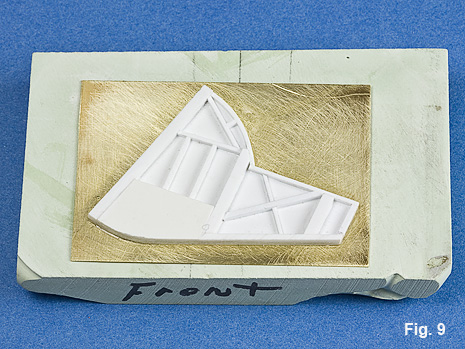
The construction of the gear doors was done on a block of plaster that was shaped to correspond to the curvature of the underside of the wing, Fig. 8. The internal structure was then cemented to brass sheet stock that had been given a curve to match the jig, Fig. 9.

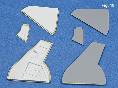

The brass is trimmed away to provide lip around the door. All the doors were done in the same fashion, Fig. 10. Note the relief of the strip at the base of the main gear door. This was simply done with a sharp instrument against a straight edge. The finished gear and door assembly are shown in figures 11 and 12. The wheels and tires were machined from acrylic rod stock.

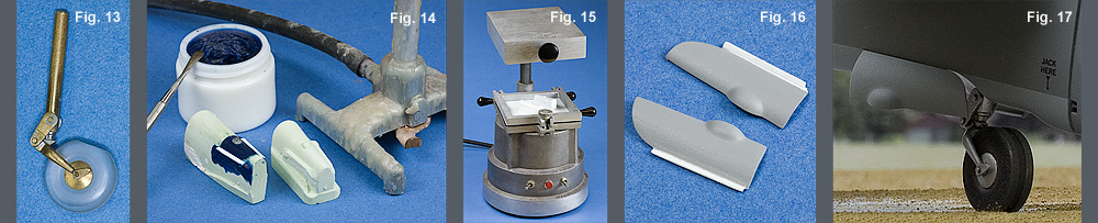
The tail gear was done from brass and the tire is an acrylic turning, Fig 13. I used a combination of a plaster form, carving wax and plastic to create a finished plaster form for the tail wheel doors, Fig. 14. The doors were vacuum formed over the plaster cast, Fig. 15. The doors were trimmed to shape leaving a lip at the upper edge for mounting, Fig. 16. This finished tail wheel and door, Fig. 17.
With the major construction done, my attention turned toward finishing techniques. One technique that I had employed successfully in the past was to scribe my panel lines into the paint rather than prior to painting. My personal feeling is that this results in a much finer panel line. One of the tricks is to choose a proper undercoat. If you were trying to simulate an aircraft that operated in extremely dusty conditions, an earth basecoat works great because it gives the appearance of dust having settled into the panel lines. In this case though, I opted for dark panel lines, so I chose DuPont dark gray lacquer primer, Fig. 18. One of my favorite airbrushes for applications of this sort is the Iwata HP-BE2, Fig. 10. This airbrush has the uncanny ability to apply large amounts of extremely well atomized material. The model was masked off, Fig. 20. The entire airframe, sans the rudder, was given several coats of primer with sanding in between to work out any imperfections. Note that the various blisters as well as the ducting from the chin intakes have not been placed. These will be done later so as to ensure very clean and controlled definition.

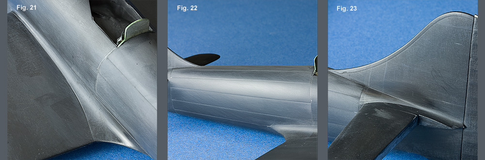
The overlapping panels that are so prominent on the aft section of the fuselage, as well as the fillets, were simulated with extra applications of primer, Figs. 21 – 23.