The Hawker Tempest was first conceived in 1940 as a developmental solution to the short-comings of the original Typhoon. In an effort to control compressibility, the Tempest incorporated a new elliptical wing that was 5” thinner than the Typhoon wing. The thin wing offered only restricted space for fuel, so 22” was added in front of the cockpit, allowing the fitting of a 76 gallon fuel tank. The increase in length in front of the center of gravity necessitated increasing the area of the tail surfaces, especially the vertical stabilizer. The Tempest V used the same engine and radiator setup as the Typhoon. The Tempest first became operational in April 1944. They saw their first actions, in very limited numbers, during the D-Day invasion. Although the majority of their service was spent with the 2nd Tactical Air Force, Tempests were probably most notable for their participation in the anti V-1 campaign known as operation “diver.” With a top speed of 435 mph at 17,000 ft, it was one of the few aircraft capable of combating the V-1. The Hawker Tempest F.Mk.V Series II was powered by a Napier Sabre IIB 24 cylinder, liquid cooled, Horizontal-H engine that provided 2,420 h.p. Armament consisted of 4 20mm Hispano Mk.V cannons.
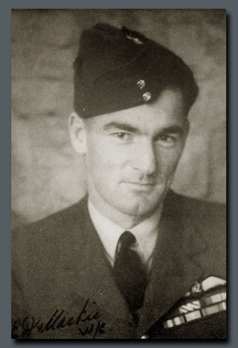
This model depicts an aircraft of 80 Squadron in March of 1945. It served most frequently as the mount for Squadron Leader E. D. Mackie. Nicknamed “Rosie”, Evan Mackie was a New Zealander who first saw action in the UK flying Spitfire V’s with 485 Squadron. Still flying Spitfire V’s, Mackie was posted to North Africa where he flew with 243 Squadron and would eventually claim 12 ½ victories. His next posting was Italy, were he would command 92 Squadron and add an additional 2 ½ victories to his total. From May to November of 1944, he returned to the UK to be stationed at Headquarters of Fighter Command. After converting to Tempest V’s, he would briefly serve with 274 Squadron until assuming command of 80 Squadron in January of 1945. Just prior to the end of hostilities, he was promoted to Wing Leader. While flying Tempests, Mackie would raise his score to 20 and three shared. He would finish the war with a DFC & Bar, DSO, and a US DFC. After the war, he returned to New Zealand to work as an inspector and electrical engineer. He passed away in 1986 at the age of 68.

Why model the Tempest Mk. V? Indeed, the question of whether to model a particular subject is something I ask at the beginning of any project, but it is especially true of a protracted scratchbuilt project. Invariably, my reasons center around a blend of historical significance and aesthetics. With regard to these elements the choice of the Tempest would, on the surface, seem inconsistent. Historically, it had a very short service life and seemed to lend no contribution to the war effort that could not have been met by other aircraft. The large chin radiator cannot be considered aerodynamically advantageous and might call into question the aesthetics of the airframe. However, in some inexplicable way, the Tempest Mk. V blends together a number of elements into an extremely seductive package. Perhaps it is the limited production that lends itself to rarity. The massive horsepower is certainly conveyed by the brutish nose architecture and large size of the airframe. Curiously, there is a grace about this aircraft as you take in the beautiful elliptical wing and the curves of the fuselage. Curves that somehow perfectly blend that huge chin radiator into the whole form. For me, the Tempest Mk. V represents an enigma symbolized by a most appropriate name.
In keeping with the spirit of the prototype, the construction of the model was a bit convoluted and spanned some dozen years between when it was started and when it was finished. The model was begun in 1995 and progressed quite rapidly. I began with a wonderful set of plans from A.L. Bentley and a limited amount of prototype information. A word about the lack of photographs depicting the early phases of construction of this model - I had written a number of magazine articles and was getting rather burnt out due to the constant stopping for photography. Transparency film was the order of the day and its latitude was much less than that enjoyed by today’s digital media. Furthermore, there was time involved in processing which put a delay in evaluating the progress photos and reshooting if necessary. Hence, I decided that I wanted to do a project simply for myself with a minimum of interruptions. I reckoned on submitting photographs of the finished model for a “gallery type” article. Unfortunately, this decision led to very few early “in progress” photos.
The fuselage was constructed in the same fashion as I had used for previous projects. I am showing photographs from the construction of the Boeing 314 Clipper as an example. The fuselage shape was generated with clay between styrene cross-sections, Fig. 1. A plaster mold was generated and the fuselage laid up in fiberglass, Fig. 2.


The mounting for the propeller was turned from bass and cemented in place, Fig. 3. The brass mount and the spinner aid in refining the shape of the fuselage, Fig. 4 – 5. This method is extremely useful for any aircraft having an inline engine and spinner because it helps maintain a consistent flow of the line from spinner to fuselage.
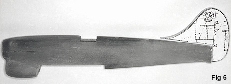
The vertical stabilizer was cut from sheet acrylic using a copy of the Bentley plan as a guide, Fig. 6. The fuselage was mounted on a board to help me visualize the alignment of the empennage, Fig. 7.
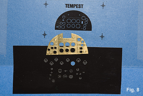
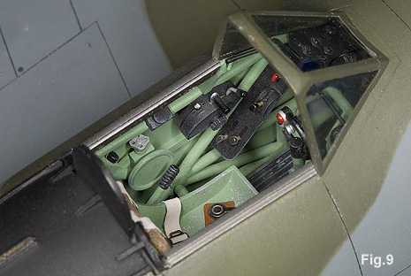
The cockpit was constructed with a variety of styrene rod stock, vacuformed seat, and machined brass details, Fig. 9. The instrument panel was a brass etching with photo-negative instrument faces, Fig. 8.
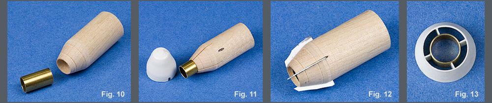
Before the wing goes to place, it is also necessary to fit the radiator. The Tempest was fitted with several different styles of carburetor intakes and probably the most common at the time was one that aided in the reduction of dust into the system. It functioned as a pair of barn doors and its aesthetics were quite similar. I chose to use the original style intake solely on the basis of character; it just says Tempest. Like many of the components of the Tempest, it was a bit of a challenge to reproduce. A piece of dowel was turned to form the shape in the first frame. A hole was drilled in the center to accept a piece of brass tubing, Fig. 10. Styrene was vacuum-formed over the wood form, Fig. 11. The tubing was placed in the wooden form and vanes were cut from .010" sheet styrene so that they fit squarely against the brass tubing, Fig. 12. The excess (shown in the third frame) was trimmed away. The front section was cut off the vacuum-formed piece and it was refitted over the form. Liquid plastic cement was used to tack the vanes to the outside piece. The whole assembly was removed from the jig and all the joints were reinforced with cyanoacrylate cement, Fig. 13.
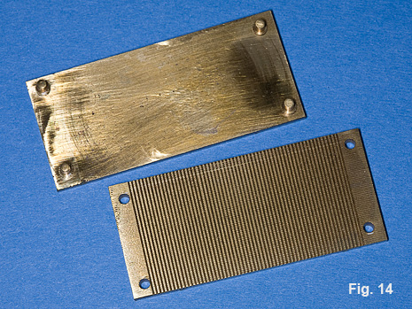
I could not find a large enough piece of material with a suitable radiator pattern in it. A die was machined to press mold a piece of styrene into a radiator pattern, Fig. 14. A piece of styrene is clamped between the brass plates and then placed into an oven.

My greatest regret for lack of in-progress photographs is in regard to the construction of the wing. I will do my best to describe my methods after the fact. The laminar flow wing of the Tempest is thin and has a similar planform as the Spitfire. In short, it is a beautiful wing. The major difference between the two wings is that the dihedral of the Spitfire wing begins at the root while the center section of the Tempest wing is straight to the gear leg with a cranked outboard span. The wing is just thick enough to accommodate the main gear and tire. My initial concerns in the construction of the wing, was to ensure the alignment of the out portions of the wind and create a structure that was sufficiently strong and resistant to warpage over time. My preferred material is a wood core sealed with polyester resin. The diagram below depicts the method I used to create the basic structure. The raw material is indicated in Figure 1. The wing planform is cut and the airfoil has been developed with the aid of a belt sander. The wing was then sealed with the polyester resin and hand sanded to final shape. Fig. 2. Note that the top of the wing is straight to the tip while the undersurface tapers from the break to the tip. A partial cut is made at the line where the wing will break. This is indicated by the red lines in Figure 3. Two grooves are cut across each of the previous cuts. Brass wire is cemented into each groove with a mixture of cyanoacrylate cement and dental resin, Fig. 4. Note that the wire is flush with the upper surface of the wing. Another cut is then made on the underside so that the only attachment of the outboard wing sections is by way of the brass wire, Fig. 5. The out board sections can now be cranked to the proper angle and the gap sealed and filled with cyanoacrylate cement and dental resin, Fig. 6. An explanation of the use of cyanoacrylate and dental resin can be found here.


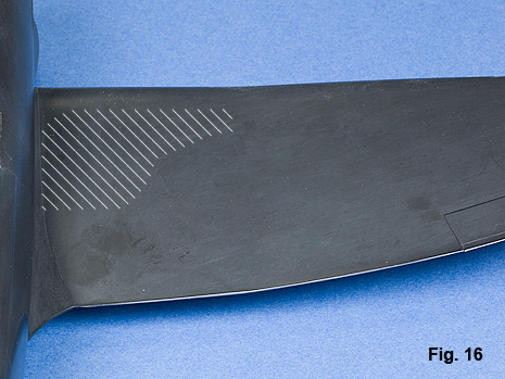

The construction of the gear well began by creating a wood form of the well shape over which styrene could be vacuformed, Fig. 15. The Tempest wing is so thin; it only made sense to just cut right through the wing to place the gear well. Cutouts for the vacuformed gear wells were made all the way through the wing. Figure 16 uses a later photograph to illustrate the technique. In reality the wing had not been mounted yet. Before placing the gear wells, I inlaid a piece of styrene on the underside of the wing. Figure 17 attempts to illustrate that point. The final opening for the gear well was cut into the inlaid styrene. The gear well was then fit into the cutout using the underside outline for final alignment and the surrounding upper wing area to establish height. The upper wing surface was then filled with the cyanoacrylate / dental resin mixture and sanded flush.
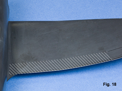
I had decided that dropping the flaps would add extra detail as well as demonstrate how large the flaps really were. The trailing edge of the wing at the location of the flaps was cut out and replaced with sheet acrylic to the depth of the centerline of the wing, Fig. 18. The acrylic was sanded down to be consistent with the upper contour of the wing. The flaps were formed from styrene sheet and square stock. A steel wire was used to simulate the rod on which the flap operates. The steel wire helps keep the styrene from warping, Fig. 19.

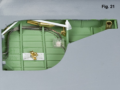
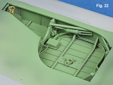
The wing was mated to the fuselage. The contour of the lower fuselage over the center of the wing underside was added with a piece of shaped basswood, Fig. 20. The wing fillets were developed from a mix of dental acrylic powder and gap filling cyanoacrylate. The gear wells were detailed with a mix of brass and acrylic machinings along with small diameter solder, Fig 21. The finished gear wells are shown in their initial coat of interior green, Figs. 22, 23.