The USS Washington was laid down in June 1938 at the Philadelphia Navy Yard and commissioned in May of 1941. In company with it’s sister ship, North Carolina, they were conceived as the U.S. Navy’s first “fast” battleships. Most often serving as the Battleship Division flagship of Admiral Willis A. “Ching” Lee, the Washington would spend from September 1942 until the end of hostilities serving in the Pacific Theater. Throughout here wartime service, she would loose no man in combat.
Washington’s most memorable engagement occurred during the second battle of Guadalcanal (fourth battle of Savo Island) on November 14-15 1942. Washington, along with South Dakota and four destroyers, engaged a superior Japanese force of two heavy cruisers, two light cruisers, 9 destroyers and the battleship Kirishima. Due to mishandling, South Dakota’s electrical circuits were out of order after her initial salvos. Sustaining numerous hits, South Dakota would become disabled and was forced to retire from the battle. As the battle developed Washington and Kirishima found themselves embroiled in a head to head slugfest. Using radar directed fire, Washington was able to score at least nine hits with her 16” main battery and 40 hits with her secondary 5” battery leaving Kirishima burning and exploding. Kirishima was later abandoned and scuttled. In addition to enemy gunfire, Washington skillfully maneuvered to evade numerous Japanese torpedoes to emerge from the battle undamaged.
At the end of May 1943, Washington returned to Pearl Harbor for repairs and a refit that would see her anti aircraft battery increased and upgraded with quad 40mm Boffors and many more 20 mm mounts. As the Naval war in the Pacific wore on, the major threat came from the air, especially with the appearance of the Kamikaze. Probably the most harrowing fighting of Washington’s career occurred during bombardment actions against Iwo Jima and Okinawa. Washington would finish the war with 13 Battle Stars. Washington was placed out of commission in June 1947 and sold for scrap in May 1961.
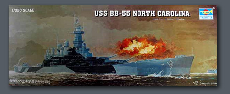
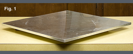
The model depicts the USS Washington at the time of the engagement with Kirishima. The basis for the model is the Trumpeter 1/350th scale kit of the North Carolina. The construction began with the hull. The bottom portion of the hull in my kit was not flat. To correct this problem, I cemented a piece of ¾” hardwood plywood to the bottom surface of the bottom hull half. I used 30 minute epoxy and placed a heavy piece of plate aluminum on top of the hull bottom while it cured for several days, Fig. 1.
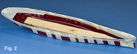
Prior to assembly, the straps across the upper hull half were removed. The upper and lower hull halves were positioned together with masking tape and cement was applied in sections, Fig. 2. Working in section facilitates making small adjustments to improve alignment (the hull in this photo is the Massachusetts, but the technique is the same).
I next turned my attention to the deck. Trumpeter molded the deck in three pieces and placed the joints in the most conspicuous places. In addition, the kit deck replicated the North Carolina in a late war fit so there were a number of details that would have to be modified. Both of these hurdles made it more attractive to scrap the kit deck and fabricate my own. I began by cutting a one piece sub-deck from .060” styrene. This was cemented in place of the original deck. This surface was sanded to insure that deck and hull sides were even.
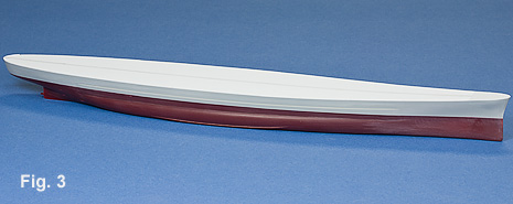
For the deck, I used N scale car siding from Evergreen. It is .020” thick and supplied in 24 lengths that make it ideal for a seamless deck. The first step was to cut a small piece for the steel forward deck. This was cut from the scribed siding and cemented in place with the scribing facing down. A piece of scribed siding was cut for the remainder of the deck. I marked a centerline on the sub-deck and the scribed decking to aid in alignment. Once cemented to place, I removed the excess material to blend it in with the hull sides, Fig. 3.
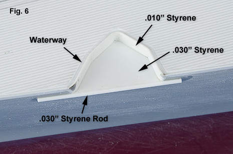
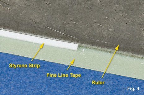
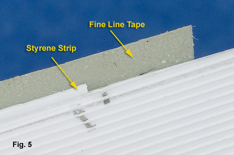
Another reason that I wanted to avoid using the kit deck was so that I could replicate the waterway that ran the perimeter of the deck. The kit supplied deck was designed to fit inside of the hull sides which left an unsightly gap at the joint. I went about establishing the waterway by first cementing a piece of .010” x .020” styrene strip around the edge of the deck. My technique was to apply the styrene strip to the sticky side of a length of 3M Fine Line tape, Fig. 4. The Fine Line tape has a nice combination of rigidity while still allowing for flexibility to adapt to the fore and aft rise of the deck. A ruler was used to insure that the styrene strip was straight on the tape. The tape was stuck to the side of the hull so that the styrene strip was in contact with the deck, Fig. 5. A bit of Weldon #4 tacked the styrene strip to the deck. I did this around the entire perimeter of the deck.
Next up was the anchor washboard cutout in the port bow. The cutout was lined with .010” styrene and blended into the adjoining strips, Fig. 6. Once all the strips were in place, I was able to carve in the depression that represents the waterway. I did this with a dental instrument known as a chisel.
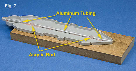
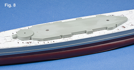
Construction of the superstructure began by separating the first level from the cast deck. To aid in location and fixation of the superstructure, I placed two studs machined from acrylic rod into which I inserted short lengths of brass rod. In order to keep the first level of the super structure flat, I cemented aluminum rod to the underside between the acrylic locating studs, Fig. 7. Corresponding holes were drilled along the centerline in the main deck, Fig. 8.
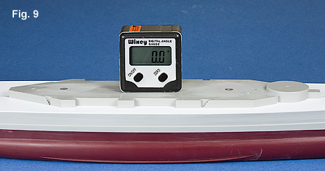
As produced, the kit’s first level of superstructure is significantly taller than it should be. I reduced the height of the superstructure so that after I added some of the .020” scribed stock, the final height would be correct. I leveled the superstructure with the aid of Wixey digital angle gauge, Fig. 9.
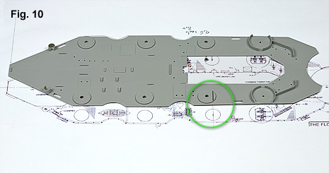
The kit supplied decking for the top of the first level suffered much of the same problems as the main deck. In addition, the location of the forward twin 5” mount was incorrect, Fig 10. I replaced the deck with the same material used on the weather deck. I also applied an edge in much the same fashion only I did not care in a waterway.
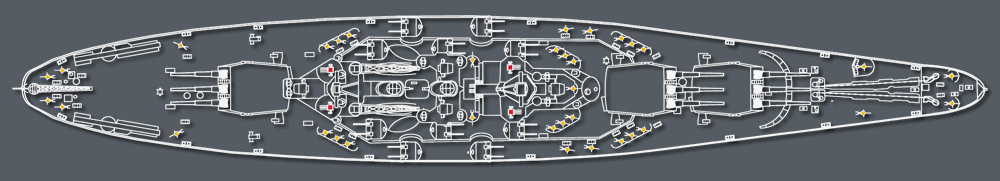
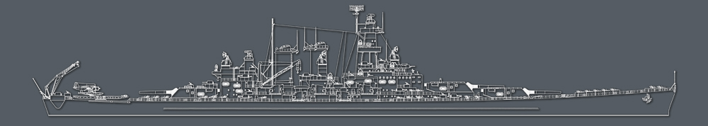
The type and position of the Washington’s anti-aircraft mounts at the battle of Guadalcanal are shown in the drawing below. The 1.1” mounts are shown indicated with red squared and the 20mm mounts are shown with yellow dots.
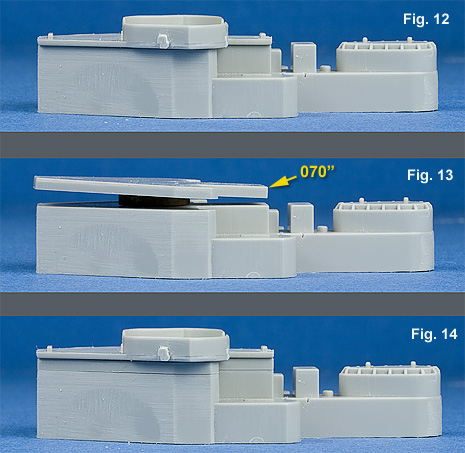
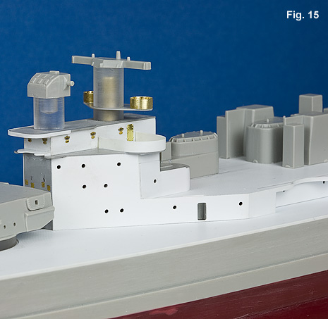
After the decking was cemented to place, I began assembling the aft island superstructure. As supplied in the kit, the height of level 3 is incorrect, Fig. 12. I added an additional .070” to the top of level 3, Figs. 13, 14. Once the aft island was cemented to place, I used .010” styrene to sheath the vertical surfaces of the first level of the superstructure along with the island. The balance of the aft island superstructure was scratch built to better correspond to prototype dimensions as well as backdating the configuration, Fig. 15.
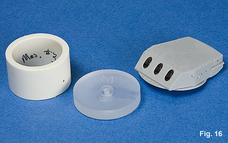
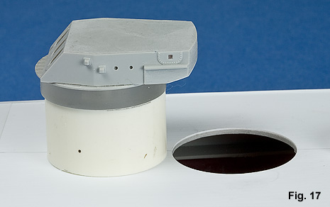
As supplied in the kit, the main battery needed much improvement. I assembled the turret sides, filled all the gaps, and then sanded everything smooth and straight. Since I had scrapped the kit’s main deck, I needed a different method to mount the main battery. Holes were cut in the main deck and ringed with styrene strip. Acrylic disks were machined to fit precisely into the openings. The disks were supported by short lengths of pvc pipe that rested on the wood that was glued to the inside of the hull. This insured that the mounts were parallel, Fig. 16, 17. An additional styrene shim was added to the top of the #2 turret mount to correct the height.
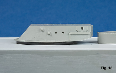
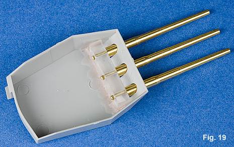
The turrets were also a bit too tall so I milled off an amount of material from the bottom edge of the turret tops before they were mated to the bottom half, Fig. 18. I used barrels from the Lion Roar detail set. For mounting, I modified the barrels by cutting off the short mounting stub, drilling out the ends, and fitting a substantially longer piece of brass rod. This provided a much more positive alignment. I milled acrylic blocks that were drilled to accommodate the barrels. The blocks were cemented to the inside of the turrets, Fig. 19.
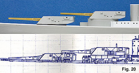
Ultimately, I think I was able to correct the kit problems with the basic shape and architecture of the main battery and bring it more in line with the drawings, Fig. 20.
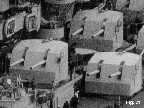
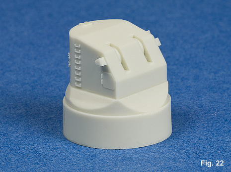
The twin 5” mounts provided in the kit are made up of four pieces that are nearly impossible to assemble while preserving any amount of detail. I ordered replacements from L’Arsenal, but discovered that the turrets on the Washington had a different shape, Fig. 21. The turrets supplied with the Tamiya Missouri are correct in shape and size with the exception of the elevation slots which are a bit thin. I took the easy way out and modified a Tamiya turret by milling out the elevation slots, fitting the shields and rear hatches, and machining new sighting scopes. I sent the pattern off to Paul Fisher (Fisher Model and Pattern) who was kind enough to cast a beautiful set of turrets. The turrets were cast with a large base so that I could chuck the turret in the lathe and precisely cut and form the base, Fig. 22.
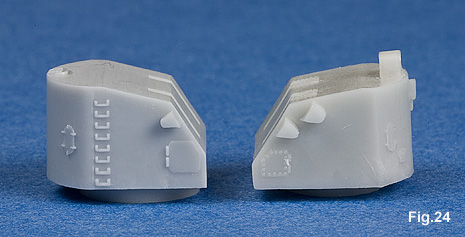
The photos show a comparison of the modified Tamiya turret (left) and the L’Arsenal turret (right). Also note the improvement in the location of the base.
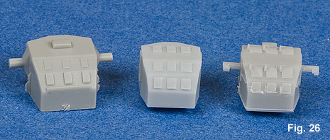
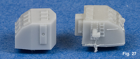
The Mk 37 gun directors supplied in the kit are quite oversized so they needed to be replaced. Again, I ordered them from L’Arsenal not realizing that the early Mk 37 had a different shape. In this case, I machined a new master for the early version. I designed my pattern so that all the detail would be added on later. I think this allowed for a squarer and cleaner casting, Fig. 27. A comparison of the kit, my, and L’Arsenal directors, Fig. 26. These were also cast by Paul Fisher.
References
Draminski, Stefan., Lipiecki, Slawomir. The Battleship USS North Carolina (BB-55). Kagero, 2007
Friedman, Norman. U.S. Battleships: An Illustrated History. Annapolis: United States Naval Institute, 1987
Shocker, Randall S. USS North Carolina: Technical Reference 1. Oxford: Oxford Museum Press, 2000
Stern, Rob. US Battleships in Action, Part 2. Carrollton: Squadron/Signal Publications, 1984
Wiper, Steve. North Carolina Class Battleships, Warship Pictorial #29. Tuscon: Classic Warship Publishing, 2007